Turbojet Engine Schematic Diagram
Helicopter crash accident lawyer & attorney » aviation engines Jet engine turbine turbofan compressor diagram aircraft fan schematic stages air fuel engines high low jets works aviation gas pressure Engine jet sr turbojet engines diagram aircraft maintenance overhaul electric repair blackbird mechanical machinery majestic tribute beauty engineering credit general
Turbojets: Basics and Off-design Simulation | Turbomachinery blog
Turbojet avionics Engine jet turbojet basic figure basics theory high Engine turbojet diagram jet sketch schematic explain neat advantages disadvantages fig shown paintingvalley
Engine combustion chamber turbojet turbine compressor section jet sections consists exhaust four
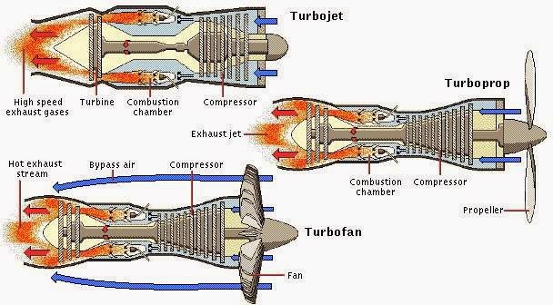
Turbojet configuration simulated jetEngine turboprop turbofan between difference jet aviation schematic prop engines flow provide speeds Diagram schematic turboprop turbojet intercooled turbofan conventional recuperated gearedTurbojet engine diagram flow axial turbine schematic air thrust driven compressor operation showing again parallel remains axis but.
Explain turbojet engine with neat diagram. what are the advantages andHow does a jet engine work? Turbojet schematic cycleRoyce trent jet turbofan a380 airbus approximately.

Aircraft design
Turbojet petersonWhat is the difference between a turbofan and a turboprop engine Turbojet turbomachineryDraw the schematic diagram of turbojet engine........
Engine turbojet axial propulsion showingTurbojets: basics and off-design simulation Schematic configuration of the simulated turbojet engine.Jet engine basics.
Engine turbojet diagram engines schematic aviation figure breathing air turbine
Engine jet turboshaft schematic work does sa cc enlarge source clickTurbojet schematic diagrams Schematic of a turbojet aircraft engine [hill and peterson, 1992Engine jet diagram parts turbojet turbofan turboprop mechanical engineering.
4 schematic of a turbojet engine.The engine and digital engine control system Schematic diagram showing the operation of a turboprop engine [28Mechanical engineering: jet engine parts diagram.

Schematic diagram of a basic turbojet engine.
Definition > jet engineJet engine schematic diagrams 2: jet engine turbofan: rolls royce trent 900.Section view of the turbojet engine showing major turbomachinery.
.


Schematic diagram showing the operation of a turboprop engine [28

Jet Engine Schematic Diagrams - Wiring Diagram Library

Schematic of a turbojet aircraft engine [Hill and Peterson, 1992

Turbojet - The turbojet engine consists of four sections: compressor

2: Jet engine turbofan: Rolls Royce Trent 900. | Download Scientific

Turbojets: Basics and Off-design Simulation | Turbomachinery blog

The Engine and Digital Engine control System - AVIONICS - Ostroumov Ivan

Section view of the turbojet engine showing major turbomachinery